

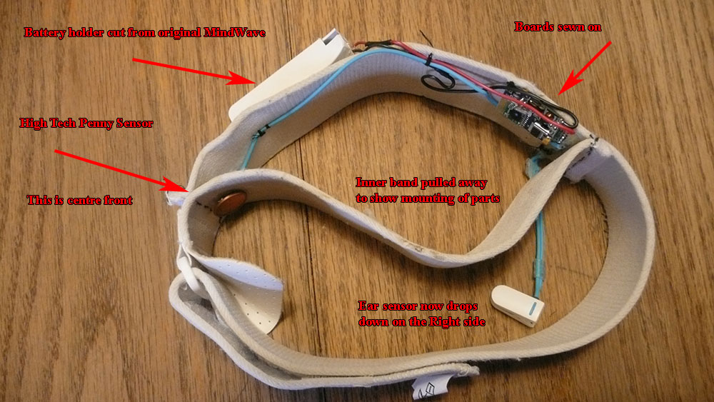
First dream captured with modified NeuroSky MindWave. Anyone familiar with the MindWave knows its design makes sleeping with it on nearly impossible. I took mine apart and remounted the boards, contacts and battery (crudely) in a elastic headband. Now it is possible to sleep with it on.
Download entry as Lucid Scribe Data (LSD) or Comma Separated Values (CSV).
UPDATE:
Thought I’d do the process in bullet form. To be used in conjunction with the attached pics. Unfortunately I didn’t take step by step pics but it is really pretty simple. If I forgot anything feel free to ask.
- Remove all the stickers from the mind wave including the large circular one that says NeuroSky MindWave. They just peel off.
- Unscrew everything
- The blue wires Going to the forehead sensor can be carefully pried out of the sides.
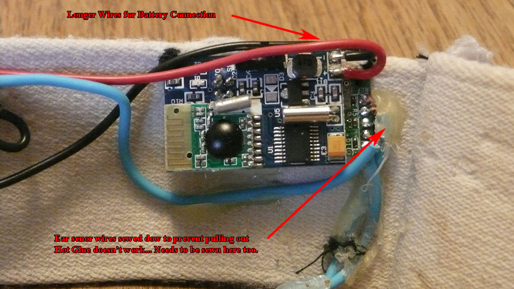
- Gently remove the boards and refer to pics for wiring scheme. These wires/connections are fragile!
- Buy a battery holder or cut away the original one and add wires to be able to mount it in a more comfortable position.
- Adapt or replace the forehead sensor
- Mount into headband as suits your needs.
- Sleep, Dream, Be Amazed


Thats the mod I’d like to do with my MindWave. If you have pics or tips to share it would be appreciated. Thanks, Bill
Tom sent in some pics and the entry has been updated!
Elite! Did any of the recordings make it into your dreams?
Not Yet. So far just used the MindWave to see if all works OK.
I see the penny electrode is rapidly tarnishing. But trying again soon.
Thanks for the pics and updated info! The penny electrode is nice touch – Bill
Can you talk more about the software side of all of this? Also the headband is connected to a computer via usb all night?
The software is available as freeware from lucidcode and I have already released some of the more interesting parts as open source: Lucid Scribe – ThinkGear EEG Plugin.
The NeuroSky MindWave headset is connected via Bluetooth and eats a battery each night, but other plug-ins, like the Halograph FM and LightStone IOM, need to be connected via USB.
Regarding the copper wires that are alongside the sensor wires: what do they actually do? Especially for the electrodes that go on the ear (passive electrode?). I was doing the mod and in trying to extend those connections, I disconnected the sensor wire and the copper wire from the clip and while I think I still get good readings when I test it so far, I’m not knowledgeable enough to acually know, and I can’t find the wiring for the insides of the ear clip. Thanks for any help!
The copper wire shielding outside the sensor wires are soldered to the board’s ground plane, and act to shield against RF and 60Hz noise from the environment. You will note that there are two electrodes inside the ear clip, one for the shielded reference and one for the RLD. The center RLD ground works well to remove the impact of this noise for the most part but I recommend keeping the shielding especially if you are near mains wiring or transformers.